Hi All,
Well after downing a few Panadine Forte capsules I've decided that I can now write the procedure on how to align both the
REAR and
FRONT rollers on a
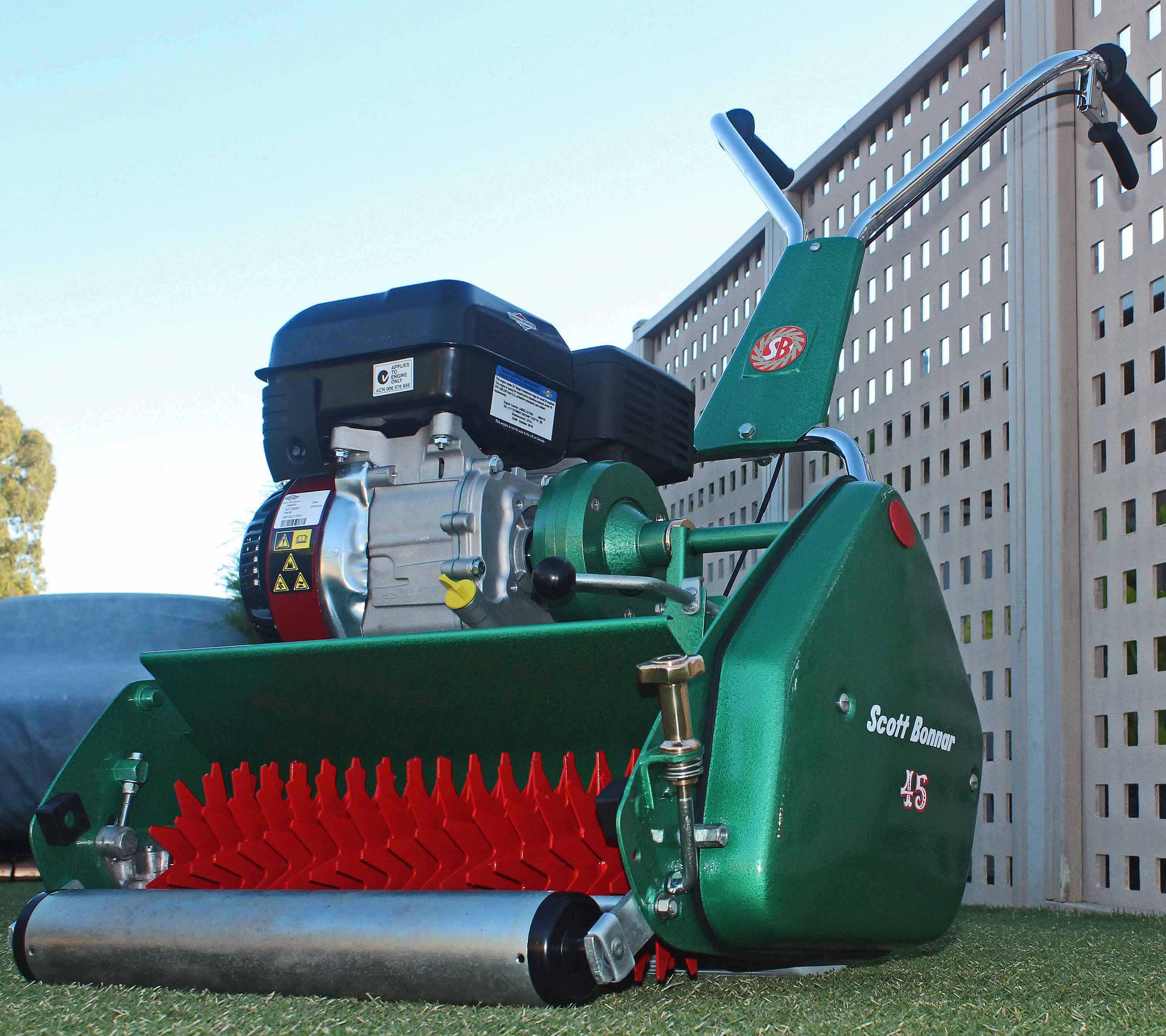
Model 45 Scott Bonnar Cylinder cut mower.
Firstly I've put an image up that I've drawn of the major components of a Model 45.
![[Linked Image]](https://www.outdoorking-forum.com.au/forum/uploads/usergals/2016/09/full-5156-30159-img053.jpg) REAR ROLLER POSITIONING & ALIGNMENT
REAR ROLLER POSITIONING & ALIGNMENTNow the first thing that has to be done is to install the sole plate complete with a new bed knife attached. Place in situ and install all the 4 bolts in through the sole plate and out through the side plate, thus the nuts are on the outside. Make sure that all the bolts and holes are free of grime etc. so that the sole plate will sit correctly within the chassis without any interference from any foreign matter. Now tighten the 4 nuts and bolts diagonally until all are tight.
Next ensure that you have the
NON slotted bearing cap on the left hand side of the rear roller with the spacer ring installed between the cap and bearing. The
slotted cap fits onto the right hand side and has no spacer ring. Slotted / elongated holes, same thing.
****PLEASE ENSURE YOU ARE USING NEW ROLLER BEARINGS !Now install the bolts through the left side bearing cap and out through the side plate, next wind on the nuts and spring washers and tighten them, the LHS cap can be rotated at any part of 360 degrees as the holes are all equi-spaced. Make sure that the RHS of the roller is supported and that you don't just have the weight of the roller stressing the LHS mounting components.
Ensure that the Right Hand bearing cap has the perfectly round hole facing towards the front of the machine and the slotted / elongated holes towards the rear. These slots / elongation provide the adjustment for leveling the rear roller up and down within the chassis and line up with the bed knife. Now tighten up the
LEFT SIDE nuts ONLYIf you look at the diagram that I've drawn you'll see that there is an alignment tool showing that must sit flush with the bed knife and also the bottom of the rear roller.
There is a generic alignment tool commercially available, but as you will probably only have to do this job once or twice in your life you can easily make this tool up out of a narrow piece of solid timber. Make it up as per the diagram using the left hand side of the mower and ensure that it sits perfectly flush across the bed knife and then just touches the most lower point of the roller.
BTW this has to be done with the mower lifted up off the ground by using two milk crates etc.underneath each side plate.
Ensure you have extra weight on the outer side of the milk crates to counter act the force being placed on the crates on the inner edges by the mower.Once you have made this tool and are happy with its fitting on the left hand side, all you have to do is slide it across to the Right Hand side of the machine and lift the RH side of the rear roller so that you replicate on your gauge the same flushness as it appears on the left side. Do up the front nut on the RH cap lightly (this bolt is used as the pivot point) so that you can do the lifting and lowering. Once you are happy all you have to do is tighten all three nuts securely and you can consider your rear roller as correctly aligned.
FRONT ROLLER ALIGNMENTThe very first thing that must be done before any accurate alignment is achieved is to ensure you have NEW end caps in your roller tube assembly. If your roller is of the Series 2 variety it will utilise the black plastic end caps. Just about every mower has slight to moderate or even massive wear on these two components and this has to be rectified before any adjustment is attempted. Also the roller shaft has to be wear free to achieve a satisfactory result, if in doubt replace it with a new one.
If you have the earlier Series 1 machine that uses the solid Engine deck (not the twin rail) you will find that you have diecast end caps with brass bushes installed. These end caps are riveted into place via 3 rivets in the roller tube. For these sadly there are no replacement bushes available commercially so you must either change to the plastic caps or compensate for the wear by holding the roller upwards while taking measurements or alternatively let it hang down and not apply any pressure when taking measurements on both sides.
All that is required to do this alignment is a good straight edge that will reach from the bottom of the rear roller to the bottom of the front roller while the machine is still raised off the ground and supported by it's side plates.
A small note on what happens to front and rear rollers to move out of alignment Alignment issues generally occur by the machine being lifted or removed from a vehicle while being transported to a workshop to have service work done and when the machine is taken from the vehicle they are carelessly dropped onto either side of the rear or front roller which places an impact onto that corner of the machine. The front roller frame assembly will be twisted rather easily when careless impact is forced upon either side of the front roller assembly while the rear roller will generally be affected only on the right hand side which has the adjustable slotted bearing cap.
THE ALIGNMENT PROCESS OF THE FRONT ROLLERThere is only one method for adjusting the front roller and that is to untwist the roller frame, there is absolutely no mechanical adjustment on the front roller what so ever.
Firstly one has to wind the front roller adjuster so that the roller is at its lowest point thus replicating the front of the mower being lifted if it was sitting on the ground.
Now once this has been done you place a straight edge on the left side of the rear roller and also the LHS of the front roller. Now get a steel rule and take a measurement between the front leading edge of the bed knife and the top of the straight edge, write it down, now do the same on the right hand side and write that figure down. Basically if no major damage is obvious then take the LHS measurement as a reference point and then the RHS of the roller frame will have to be corrected to match the left hand side. This can only be done by removing the roller frame and placing the left hand side of the frame into a solidly mounted bench vice and placing a large shifting spanner on the RHS of the roller frame (the roller shaft outrigger) and twist in the direction so as that both the outriggers are parallel when sighting along the assembly frame. This sadly is a bit of a trial and error expedition, sadly there is no quick fix. Also one has to be rather gentle and use a bit of feel when doing this part of the alignment process. Patience is the key. Once you feel that the right hand side is as parallel to the left side as can be you will have to reassemble the roller and re-install into the chassis and retake the measurements. If you are within a millimetre I'd say you have achieved as good as it gets. If not, then repeat the above procedure until you are satisfied with the measurment figure. The ultimate test is to place the mower on a reliable flat surface and lightly lift the mower from one of the handlebar grips then the other to see if there is any play in the machine diagonally.
A FINAL WORD REGARDING THE MODEL 45.......... to take into considerationOne major factor to take into consideration is that the Scott Bonnar Model 45 is a
"Domestic Mower" and
NOT a commercial unit that would have adjustment facilities to adjust every component of the machine. The Model 45 was a mass produced mower to be used on the average garden lawn in the 1960's and not really to be used as a Greens Mower.
Regardless though of that statement many of us have achieved pretty good results with the 45 and thus it's probably the worlds best cylinder cut mower in the price point it was aimed at in the market place.
If you have any questions regarding the the job at hand, don't hesitate to ask questions as that's what we're here for.
Cheers,
BB.


![[Linked Image]](https://www.outdoorking-forum.com.au/forum/uploads/usergals/2016/09/full-7392-30141-img_3309.jpg)

![[Linked Image]](https://www.outdoorking-forum.com.au/forum/uploads/usergals/2016/09/full-7392-30139-sb45_rear_roller.jpg)
![[Linked Image]](https://www.outdoorking-forum.com.au/forum/uploads/usergals/2016/09/full-7392-30140-genuine_scott_bonnar_rear_tp_8702745537677201397f.jpg)
![[Linked Image]](https://www.outdoorking-forum.com.au/forum/uploads/usergals/2016/09/full-7392-30204-topic_closed.jpg)


