i did remove both valves with a screwdriver and pliers, and gave them a good sand with 2000 grit sand paper, this stuff is so fine you can use it on the cylinder bore of an engine (i have done it to my old MSAA engine and there were no issues there)
i removed all the build up on the valves and the intake and outtake ports, the intake port had a lot of metallic burrs on it that i filed and cut away, then sanded both the intake and outtake ports so that they are now relatively smooth.
I reset the valves and saned the cylinder head so hopefully the engine will run good, the only possible problem now can be the carby.
So far as the oil seal is concerned, I understood you had identified a slight weep of oil from it at the start of the exercise. To be sure the valves seal, you need to lap them. This is a simple procedure: you smear their sealing surface with some paste you can get in your local speed shop, put them in their guides to keep them central, and twirl them around for a while. Then you clean both valve and seat of the paste, and look where the paste has abraded them. If you find a continual abraded surface all the way around both valve and valve seat, you are done. After that, you must check the tappet clearance, but you need to have the camshaft and timing cover installed to do that so it is a final adjustment when you are reassembling the engine. Polishing the ports of your engine is not a normal maintenance operation, it is an engine modification that often increases the output power by a minuscule amount at high engine speed. Sometimes it decreases low speed torque a bit too; rough port surfaces are actually a good thing at low speed. Have you checked the piston ring gaps? Have you cleaned the breaker points and adjusted the breaker gap?
That is a bit mystifying - I understood the Magnetron ignition system was introduced in 1981, and your engine was made in 1974. Has it been retrofitted?
I've attempted to add three illustrations: the picture of your module; a drawing of the 60102 ignition system; and a drawing of the breakerless (Magnetron) module. It looks to me as if you have your engine's original, pre-Magnetron, breaker-type ignition system. You can clear all this up just by removing the flywheel. If I'm right, you'll find the breaker and condenser behind it.
you know i cant get the flywheel off at all, any ideas on how to remove it?
im certain that there are no points under the flywheel. There is a magnet on the flywheel which gives me the impression of it being breakerless, its almost the exact same setup as my whipper snipper which is also breakerless.
But since i cant get the flywheel off i can be absolutely sure
Your engine has points and as Grumpy said they are under the flywheel.
To remove the flywheel you can put a screwdriver under it and tap the side of the flywheel (not where the magnets are) at the same time applying pressure on the flywheel using the screwdriver and it should pop off. One other thing just spray the shaft with WD40 and let it soak for a while.
Regards,
Bruce
Please do not PM me asking for support. Post on the forums as it helps all members not just the individual.
the problem is that on inside the started clutch assembly there seems to be a nut threaded to the shaft, and looks like it may need turning. Ill give it another try a bit later today and take some pics so you can see clearly.
Also if there are not any points underneath that flywheel i will have to track you 2 down and rough you up a bit
If you get a block of wood and place it on the clutch housing and then hit it in a anti clockwise direction the nut and housing will undo. You will then be able to remove the flywheel and see the silver cover which is over the points. It has two screws holding it on.
Before you do this I would suggest have a couple beers to relax you so you can understand the directions given but if you don't understand after a couple then have a few more till it all makes sense.
Regards,
Bruce
Please do not PM me asking for support. Post on the forums as it helps all members not just the individual.
Well done tezza, neither of them goes quite as far back into history as my 60102, but the resemblance is there and the parts are probably interchangeable.
so i got the engine started yesterday and boy does it sound good.
the carby is still an issue, the whole throttle control using 2 springs and and the piece of wire is causing issues, i think im gonna rig up the carby so its direct throttle control since it causes so many problems.
Also can someone recommenced some paint for the fuel tank, the petrol strips away any paint that i put on it.
still cant get the flywheel off, but it produces enough spark to stun a bull so i wont worry about it for the moment
I think it would be a bad idea to run that engine without a governor - it won't be protected against over-revving and it won't respond to load. B&S engines are already a bit prone to throwing connecting rods through the side of the crankcase even when you don't remove their safety system that tries to prevent it. The governor is not very complicated - there are only about three parts in it. If you are having problems with the engine hunting - that is cyclically speeding up and slowing down without you adjusting the speed setting - it is not a fault in the governor, it is just lean mixture, and that is easily adjusted with one screw. I suggest you describe your issues, and see if someone can suggest a way to fix them.
well its sort of like you say, it will rev at a constant speed for a bit, then suddenly rev faster or slower. the mixture screw, doesn't affect this over and under revving at all, i can see the throttle control actually moving when this happens
Watching the throttle butterfly move is an important clue when adjusting the mixture. When the mixture is right, the butterfly doesn't move much at no load. If you can't make it rich by turning the mixture screw anticlockwise, you have a fuel feed problem (dirt in the system or a bad fuel pump diaphram). You can tell when it is rich by the exhaust smell, and it slows down a bit and opens the throttle slightly. When you turn it clockwise it should run better and faster, and the throttle should be open slightly less. Then if you keep turning it clockwise the engine will slow slightly, and the throttle will open a bit then start to work back and forth quite noticeably. At that stage you might find the big speed variations you mentioned (hunting).
i will try that, im sure its only an issue with the spring setup, im gonna get a couple of different springs and try them out as well as trying that metal wire on the different numbers to see if that will do anything, does anyone know what those numbers mean?
Another thing, ive put the rear roller back together and put everything back on the frame, Now with the engine off when i engage the clutch is the roller supposed to roll back or forward, currently it is locked so it wont roll backwards, but it engages the gears and moves the blades backwards.
I followed the images in the illustrated parts list so it look slike the 6 keys are in the right way, but im not sure, i think it may be in back to front, but it doesnt affect the running of the mower so im not gonna take it back out.
only thing left to do is to get a new fuel cap and air filter and paint the chain guard and blade guard. Im gonna leave the catcher alone for a while cos theres a heap of rust on it, and it i aint got enough paint to finish of the entire catcher, so that will be a project in itself for next copule of months.
Changing the spring on the governor will stop it from working properly. There is an air vane under the cowl. The vane is moved by air blowing from the fins on the outside of the flywheel. The vane on the 60102 is poor compared with the one on the 92908 and other second-generation engines, but it will work satisfactorily. I have attached two pictures showing the governor, from the repair manual. The second one, showing the remote controlled version, shows you which hole to put the governor spring in on the operating lever. Parts of the manual show the spring and the control rod both in the upper hole. I tried that on mine and the governor was a bit unstable, like yours, so I put it back the way it had been in the first place, which is the same as shown in the second illustration: spring in the lower hole. You might try both arrangements and see what works better. Be careful not to damage the spring. It is a close-coiled tension spring: when not being stretched, the coils should be touching each other. If they are not, the spring is stretched and is useless.
thanks grumpy, i think i have the springs in the right places, ill just have to play around with the mixture screw and the govener positions untill i get a decent running engine.
by the way where are you getting these images from, they done seem to be in the pdfs from the manuals section of the site?
I'm a bit worried when you say "springs" - the later designs have 2 springs, but the 60102 governor only has one spring, as shown in the diagrams I posted. BTW, if I recall correctly the instructions for my engine said you should start and tune that engine with the speed control in about mid-position.
You can look at any page of the manual on-line, or buy the whole thing either as a download or on CD. It doesn't cover the current series, or any of the Chinese-made engines.
The second spring on that is just a return spring for the remote control, it does not affect the governor. It just biases the speed setting lever to make it easier to adjust via a very inefficient Bowden cable, it does not affect the butterfly throttle's position. You can see a similar deal, where a monstrous additional spring was used for that purpose, on Kirby Lauson (Tecumseh) mower engines of about that period. I don't care for the mechanism - the genuine B&S one I posted seems much more elegant to me - and yours had a kinked Bowden cable right at the anchor point as well, but it has no bearing on your governor instability. So what did you do to fix the instability: tune the mixture?
i put the spring in the right holes for starters, but i had to twist and strighten the link govener so that the loop was facing toward the engine, the spring was getting stuck on the throttle mechanism and the starter cover. then i adjusted the mixture screw and the idle speed.
Also had to get some washers for the carby screws, they kept shaking loose so it was sucking air through there as well.
now it starts on the 3rd or 4th go and doesnt stop or loose power when i engage the blades or the roller. Its a bit much to ask it to start on first considering the tiny amount of pull the start has, besides the fact that its 35 odd years old.
I had to change the curve in my governor link too - it was fouling on things. The way I start mine is chainsaw style. It has a very crude, chainsaw-like choke with no spring-loaded "unloader" feature such as real carburetors have. So, I close the choke, pull the starter either once or twice, and it chugs then stops. I open the choke fully, pull once, and it starts and runs. I used your method until I looked at the choke and realised only brute force would work - now it starts more easily. I agree, mine was about fourth pull in warm weather if I didn't use the choke.
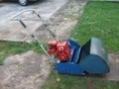
Hi Tezza, good job mate, she looks a real treat. Can you tell me why your grass deflector is so far forward?
Please do not PM me asking for support. Please post your questions in the appropriate forums, as the replies it may receive may help all members, not just the individual member. Kindest Regards, Darryl


![[Linked Image]](https://www.outdoorking-forum.com.au/forum/uploads/usergals/2011/01/full-2772-312-th_img_0174.jpg)
![[Linked Image]](https://www.outdoorking-forum.com.au/forum/uploads/usergals/2011/01/full-2772-313-th_img_0175.jpg)


![[Linked Image]](https://www.outdoorking-forum.com.au/forum/images/members/mower-monsterw.jpg)

![[Linked Image]](https://www.outdoorking-forum.com.au/forum/uploads/usergals/2011/01/full-2772-282-img_0212.jpg)
![[Linked Image]](https://www.outdoorking-forum.com.au/forum/uploads/usergals/2011/01/full-2772-287-img_0213.jpg)
![[Linked Image]](https://www.outdoorking-forum.com.au/forum/uploads/usergals/2011/01/full-2772-283-img_0214.jpg)
![[Linked Image]](https://www.outdoorking-forum.com.au/forum/uploads/usergals/2011/01/full-2772-284-th_img_0215.jpg)
![[Linked Image]](https://www.outdoorking-forum.com.au/forum/uploads/usergals/2011/01/full-2772-285-img_0216.jpg)
![[Linked Image]](https://www.outdoorking-forum.com.au/forum/uploads/usergals/2011/01/full-2772-314-th_img_0237.jpg)
![[Linked Image]](https://www.outdoorking-forum.com.au/forum/uploads/usergals/2011/01/full-2772-315-th_img_0238.jpg)
![[Linked Image]](https://www.outdoorking-forum.com.au/forum/uploads/usergals/2011/01/full-2772-316-th_img_0239.jpg)
![[Linked Image]](https://www.outdoorking-forum.com.au/forum/uploads/usergals/2011/01/full-2772-317-th_img_0240.jpg)
![[Linked Image]](https://www.outdoorking-forum.com.au/forum/uploads/usergals/2011/01/full-2772-318-th_img_0241.jpg)
![[Linked Image]](https://www.outdoorking-forum.com.au/forum/uploads/usergals/2011/01/full-2772-319-th_img_0242.jpg)
![[Linked Image]](https://www.outdoorking-forum.com.au/forum/uploads/usergals/2011/01/full-2772-320-th_img_9121.jpg)
![[Linked Image]](https://www.outdoorking-forum.com.au/forum/uploads/usergals/2011/01/full-2772-321-th_img_0237.jpg)
![[Linked Image]](https://www.outdoorking-forum.com.au/forum/uploads/usergals/2011/01/full-2772-322-th_img_9118.jpg)
![[Linked Image]](https://www.outdoorking-forum.com.au/forum/uploads/usergals/2011/01/full-2772-323-th_img_0241.jpg)


